Tascam M-208 & M-216 - How to Add Direct Outputs
If you're looking to bring vintage warmth into your DAW workflow, this guide explains how to modify the Tascam M-208 and M-216 vintage mixers by adding direct outputs to each channel. This allows the distinct sound of these classic analog mixers to be captured separately, with each channel connected independently to your recording setup.
See Tascam M-series mixers for sale. If you don’t see the model you need get in touch – we often have more stock waiting for assessment/service.
Note: This is an early draft based on internal tech notes. It’s not the final article, but due to repeated requests, we’re sharing the current version. If you have feedback, feel free to send suggestions.
Please note: the power supply on the larger M series desks will not power full implementation of direct output mods (maximum of 8 direct outs on the M216). We cannot offer further info on other models.
Overview: Direct Output Modification
This mod replaces the 8x RCA Tape In sockets with 1/4" jack direct outputs - post-fader, post-EQ, and parallel to the pan pot and effect bus.
Key Benefits:
-
Individual channel outputs for multitrack recording
-
Post-fader signal = less interference with bus output
-
Option to push both the preamp and bus amp for analog saturation
-
Behaves similarly to direct outs on the Tascam M-30 and Model 3
-
Disclaimer
Please read before proceeding:
-
No liability accepted. Attempting this mod assumes a good working knowledge of electronics.
-
We cannot respond to emails about the modification steps - though suggestions to improve this guide are welcome.
-
Your mixer should be fully serviced and electrically safe before beginning this work.
-
BEFORE AND AFTER
Rear view before modification:

Rear view after modification:

-
1. Prep the Mixer
-
Service the unit first
-
With channels removed, start by:
-
Removing metal clips from the jack plate
-
Desolder and remove the jack plate
-
Remove RCA Tape In connectors (8 on M-208, first 8 on M-216)
-
Reinstall the jack plate, attach mod jacks using the supplied plastic nuts
2. Soldering the Mod
-
Solder the positive and ground wires of the mod tail to each side of R139 (solder side of the PCB)
-
Follow the solder mask to identify ground
-
Let the cable run neatly across the back of the board to avoid interference when refitting
-


-
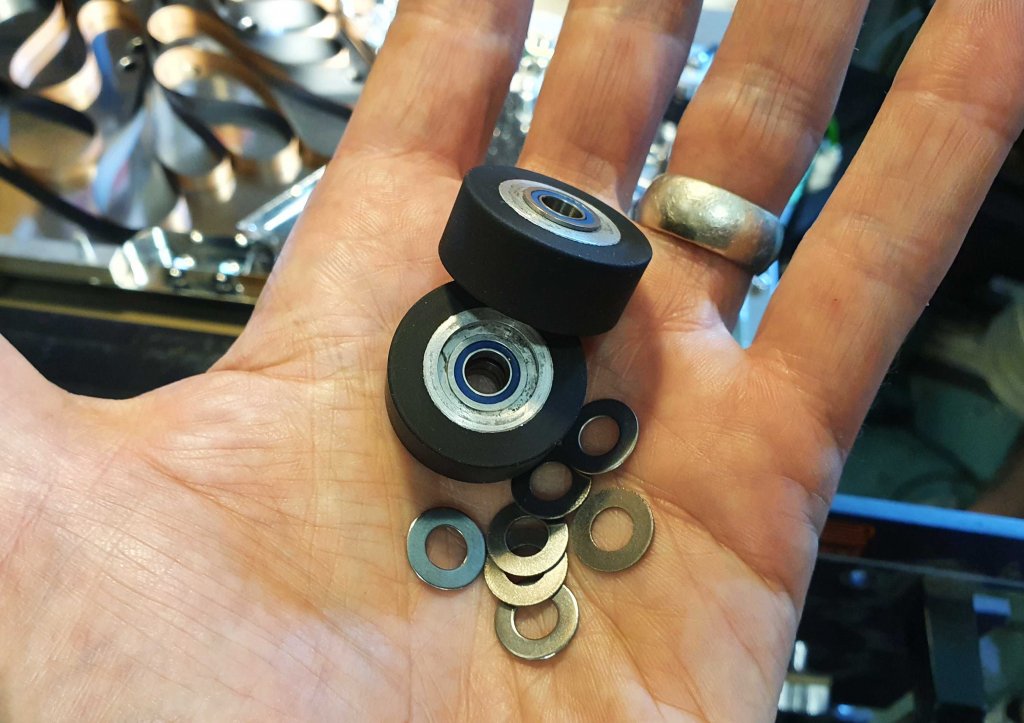
3. Building the Mod Tail
We use:
-
Neutrik NMJ2HF-S jack (check dimensions if substituting)
-
Shielded single-core wire (RS 207-5311)
-
33nF 50v Nichicon capacitor (yellow)
-
10kΩ ¼-watt metal film resistor
-
100Ω ¼-watt metal film resistor inline with the positive lead
Tips:
-
Add a small red wire to the resistor leg for strain relief
-
Heat shrink over resistor-to-core joint
-

4. Solder to Board & Jack
-
Wire the signal core to the jack’s tip and the shield to ground
-
Route the other ends to the designated PCB points
Modding All 16 Channels on a Tascam M-216
We only recommend modding the first 8 channels as the power supply on the M-216 cannot handle any more.
To mod channels 9–16:
-
Remove the entire back panel
-
Mark and drill holes for additional jack outputs
Drilling Guide:
-
Use masking tape and a ruler to mark vertically and horizontally
-
Create crosshairs (X) at center points
-
Use a punch to mark centers
-
Drill holes with a 12mm or 13mm bit

Final Notes
These instructions were prepared by the Soundgas Workshop
with thanks to Nick Allott for his original version of this mod.
Want to see available models? See Tascam M-series mixers for sale.
Soundgas LFOmo Manual
Amplify Your Studio Budget: Lock In 2025 IRS Deductions Now
Related Posts

Amplify Your Studio Budget: Lock In 2025 IRS Deductions Now

Soundgas LFOmo Manual

Soundgas Type 636 Manual
Soundgas Type 636P2 Manual

Zero Head Gain Roland Tape Echoes

Soundgas Type 636P Manual